Methods
Modeling
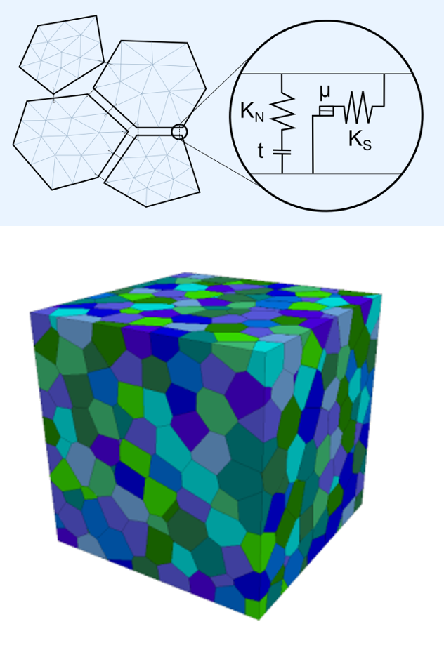
In DEM the model area is divided by single joints or groups of joints into deformable blocks. The properties of the block material (e.g. density, elastic constants) and the joints (e.g. roughness, aperture) as well as the mechanical and hydraulically boundary conditions have to be specified. The usage of different block and joint models results in a more or less realistic simulation result. The goal is to implement a new joint model to obtain better results for hydro-mechanical coupled tests.
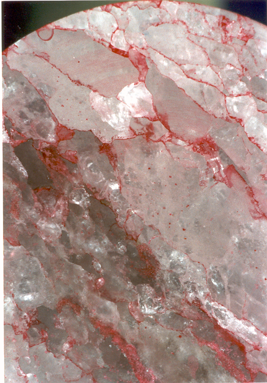
Salt is a polycrystalline material, that owes many of its properties to the nature of the grain boundaries between individual salt crystals. A numerical description requires therefore a method that can treat many different blocks, which interact via a surface model, that can describe friction and fracture. The program 3DEC (3D Distinct Element Code, Itasca) is able to handle this kind of problems, with user defined material and joint models. The figure below shows the concept of a discontinuous approach to geomechanical models.
Experimental
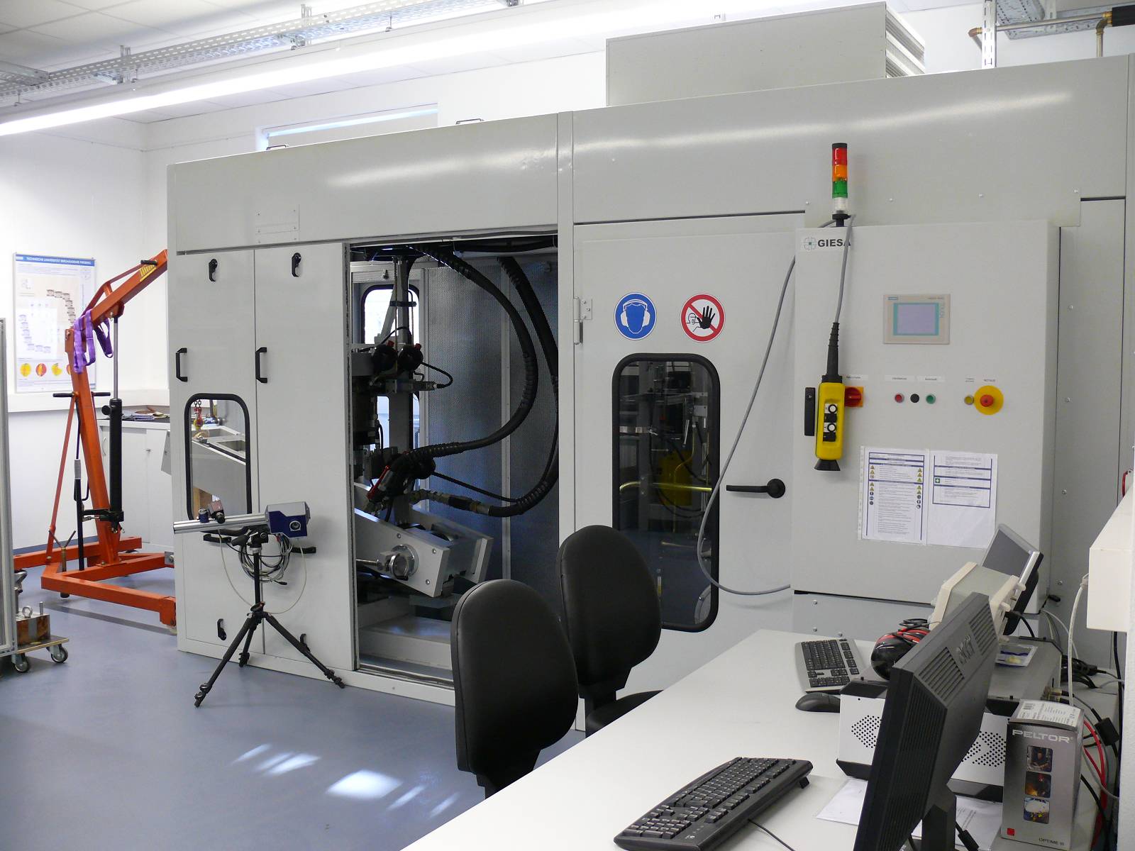
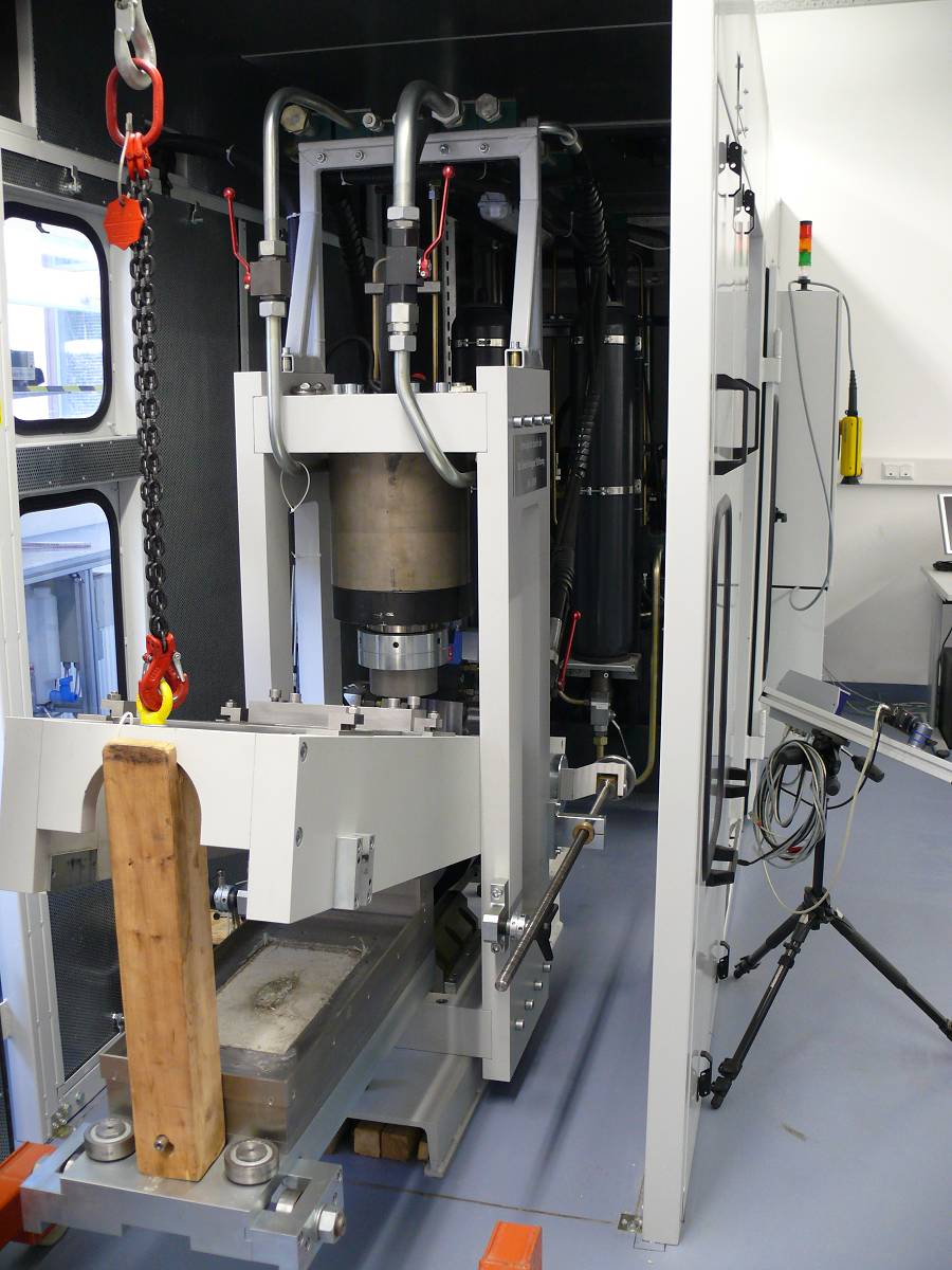
Laboratory tests in WP3 will be conducted using the large shear box device GS-1000. This unique testing machine was developed in close cooperation between the Chair for Rock Mechanics at the TU Bergakademie Freiberg and the GIESA GmbH in Wilsdruff. It consists of 4 components:
- Hydraulic aggregate
- Shear box with horizontal and vertical frame
- Electronic control unit
- Water cooling system
The most important technical data are:
- Normal force from 0 to +1000 kN
- Shear force from -300 kN (tension) up to +800 kN (compression)
- Big shear frames with surface areas of 200 x 400 mm
- Maximum shear displacement of 50 mm
- Shear velocity from <1e-7 mm/s (displacement regulation) up to 70 mm/s
- 16-bit signal resolution for all measurement
- LVDT-measurement for displacements and load cells for force-measurement
- Accuracy in displacement measurement 1 µm
Besides special programmed testing operations, the servo-controlled system is programmed for the following standard procedures:
- Force-controlled testing
- Displacement controlled testing
- Dilatancy-controlled testing
- Stiffness-controlled testing
For hydro-mechanical-coupled testing a pressure-tight shear box was developed for fluid pressures up to 100 bar. With this new device static, hydraulic boundary conditions with constant fluid pressure as well as fluid-flow conditions can be realized.
Triaxial loading and strength tests are performed in a Karman-cell in a servo-hydraulic testing machine (RBA 2500). It allows independent control of the radial and axial stresses. The samples are sealed with rubber tubes and oil is used as confining medium. Axial and radial strains can be measured.
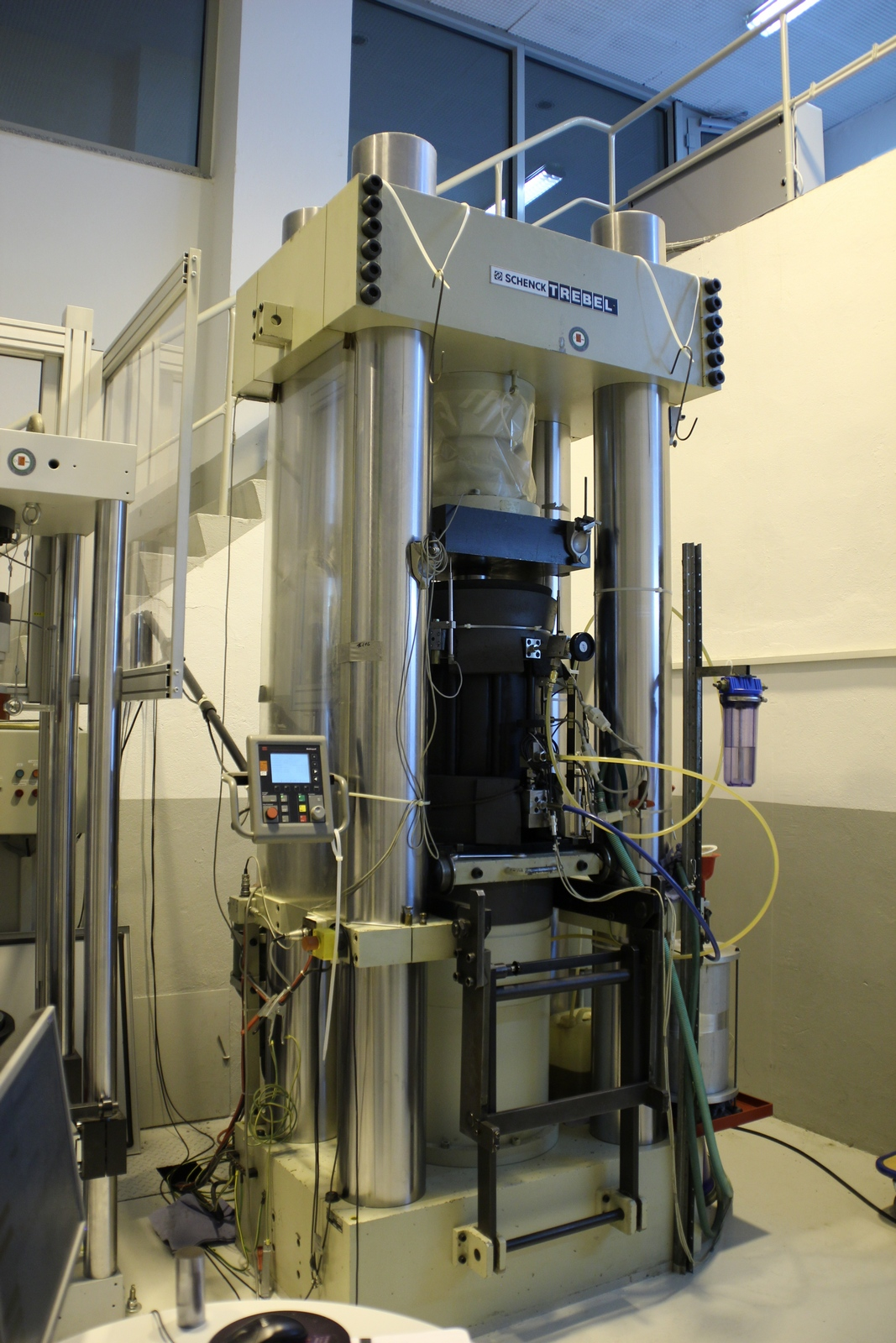
To measure the fluid (gas/liquid) transport properties of rock salt, typically the flux is measure as a function of the fluid pressure gradient and the confining stress. The latter enters Darcy's law via the permeability constant. Depending on the relative magnitude of axial and radial stresses, both axial and radial flows can be realized. If this method is applied to samples, which were pre-damaged in a controlled experiment, detailed information on the integrity of saliferous barriers can be obtained.
Experimental Platform
 In order to investigate the barrier rocks, such as saltstone, claystone and crystalline, response under the coupled thermo-hydro-mechanical (THM) processes, a series of laboratory and field tests in the scope of the GeomInt project are carried out. A graphical abstract of experimental activities is depicted in Fig. 2.4.
